
Home
>
Products > TFT LCD Module > Standard TFT LCD Module > 7.0" 800x480 LVDS IPS TFT LCD Module, 40-pin
Products
7.0" 800x480 LVDS IPS TFT LCD Module, 40-pin
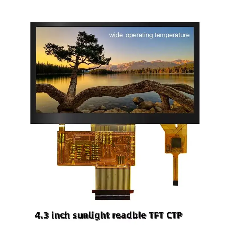
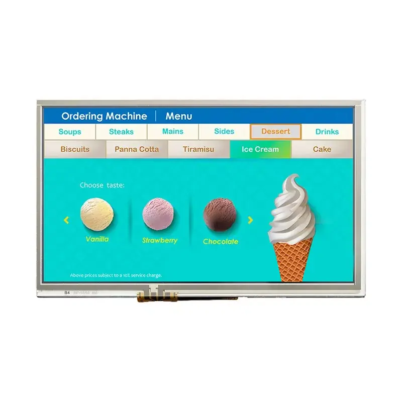
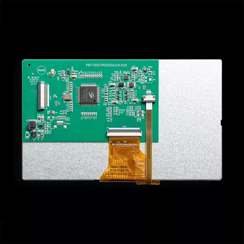
Where a display can be mounted is usually decided by mechanics, then corrected in software. The Victronix VXT700KWSA-01 removes that second step. Two dedicated pins — L/R on pin 33 and U/D on pin 34 — flip the image horizontally and vertically in hardware, so the same module works upright, upside down, behind a mirror, or viewed through a periscope without touching a line of framebuffer code or paying the performance cost of software rotation. The 7.0-inch 800x480 panel runs on an ST7277 driver over single-channel LVDS on a 40-pin connector, brightness is controlled by a dedicated LED_PWM pin, and STBYB puts the panel into standby for power-sensitive products.
Model:VXT700KWSA-01
Send Inquiry PDF DownLoad
Product Description
Flip the Picture With a Jumper, Not a Rewrite
Software rotation sounds free until you try it. Rotating a framebuffer in the MCU costs memory bandwidth and CPU cycles, doubles your interrupt load on every frame, and on a graphics-light part it can eat a noticeable slice of your frame budget. Worse, it forces a compromise: you either rotate on every refresh or you maintain two copies of every asset.
This module sidesteps all of it. The scan direction is set by two logic levels:
|
Pin |
Level |
Result |
|
33 — L/R |
H (default) |
Scans left to right — normal horizontal orientation |
|
33 — L/R |
L |
Scans right to left — horizontal mirror |
|
34 — U/D |
H (default) |
Scans top to bottom — normal vertical orientation |
|
34 — U/D |
L |
Scans bottom to top — vertical flip |
Set them once at the board level with a resistor to VDD or ground — or drive them from GPIOs if the product needs to switch orientation on the fly — and the panel renders correctly. Both pins must be tied to a defined level; neither should be left floating.
The situations where this earns its keep are more common than they sound:
- Cable exit on the wrong side. The FPC has to come out toward the connector, and that forces the panel to rotate 180°. Set L/R and U/D low and the picture is correct, with no mechanical rework.
- Viewed through a mirror or a fold-out hatch. A head-up arrangement, a folding test instrument or an inspection camera housing reverses the image optically; one pin reverses it back.
- One PCB, two enclosure variants. A left-hand and a right-hand mount, or a wall-mount and a ceiling-mount version, can share the same board and firmware, selected by a resistor stuffing option.
- Retrofitting an existing fascia. If the previous panel scanned the other way, matching it is a pin strap rather than a firmware fork.
Why LVDS Here: Distance and Noise
We also build a 7-inch 800 × 480 module with a parallel RGB interface. It is the right answer when the display sits on the same board or a few centimetres away, because the host's LCD controller drives it directly and there is no serializer to buy. This is the other answer.
|
Consideration |
Parallel RGB sibling |
This module — LVDS |
|
Signal lines |
Many parallel data lines plus sync |
4 differential data pairs + 1 clock pair |
|
Cable length |
Short — best within the same enclosure |
Longer runs between board and panel |
|
EMI behaviour |
More radiated noise, more susceptibilities |
Differential pairs, inherently quieter and more immune |
|
Host requirement |
On-chip RGB LCD controller |
LVDS transmitter — common on industrial SoMs and SBCs |
|
Connector |
60-pin |
40-pin |
General Specifications
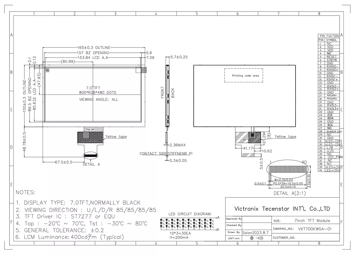
VXT700KWSA-01 is a TFT-LCD module. It is composed of a TFT-LCD panel, driver IC, FPC,a back light unit. The 7.0¢¢ display area contains 800x480 pixels and can display up to 16.7M colors. This product accords with RoHS environmental criterion.
|
Item |
Contents |
Unit |
Note |
|
LCD Type |
TFT |
- |
|
|
Display color |
16.7M |
|
|
|
Viewing Direction |
ALL |
O’Clock |
|
|
Operating temperature |
-20~+70 |
℃ |
|
|
Storage temperature |
-30~+80 |
℃ |
|
|
Module size |
Refer to outline drawing |
mm |
|
|
Active Area(W×H) |
153.84X85.63 |
mm |
|
|
Number of Dots |
800×480 |
dots |
|
|
Driver IC |
ST7277 |
- |
|
|
Power Supply Voltage |
3.3 |
V |
|
|
Outline Dimensions |
Refer to outline drawing |
- |
|
|
Backlight |
3S10P-LEDs (white) |
pcs |
|
|
Interface |
LVDS |
- |
|
Outline Drawing
Hot Tags: 7 inch TFT LCD, 800x480 LVDS display, LVDS TFT module 7 inch, ST7277 TFT display, 40-pin LVDS TFT, image flip TFT module, horizontal mirror display pin, vertical flip LCD, STBYB standby TFT, LED PWM dimming display, industrial HMI 7 inch LVDS, Victronix 7 inch LVDS TFT
Product Tag
7 inch 800x480 LVDS TFT LCD module
7.0 inch LVDS display module 40 pin
ST7277 driver IC TFT display
LVDS interface 7 inch TFT module
TFT module with hardware image flip
horizontal mirror pin TFT display
vertical scan direction control LCD
L/R U/D pin display module
LVDS display for long cable run
7 inch display remote from mainboard
Related Category
High Brightness TFT Module
Standard TFT LCD Module
Bar-Type TFT Module
Round TFT LCD Module
Transflective TFT LCD Module
Wide-Temperature TFT Module
Square TFT LCD Modules
Send Inquiry
Please feel free to give your inquiry in the form below. We will reply you in 24 hours.